Low Voltage Switchgear Design Guide: Best Practices for LV Switchboard Design
A practical guide to low voltage switchgear and LV switchboard design — the key considerations, a step-by-step design workflow, the common mistakes to avoid, and how IEC 61439 compliance is verified.
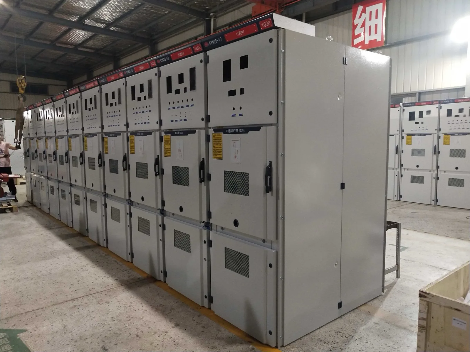
Low voltage (LV) switchgear is the backbone of any building or plant's electrical distribution — the assembly that takes incoming power at up to 1000 V AC and distributes it safely to final circuits, motors, and control loads. Getting the switchboard design right means balancing electrical performance, safety, maintainability, and cost, all while meeting the verification requirements of IEC 61439. This guide walks through the considerations, a practical step-by-step workflow, the mistakes engineers most often make, and the standards that govern compliance.
Key Considerations in LV Switchboard Design
Before drawing a single panel, settle the parameters that drive the whole design:
- Rated current (Inc) of the main busbar and the load current of each outgoing way
- Short-circuit withstand — rated short-time (Icw) and peak (Ipk) current the assembly must survive
- Form of internal separation (Form 1 to Form 4) for the required level of safety and maintainability
- Temperature rise — verified busbar and device ratings under real enclosure and ambient conditions
- Ingress protection (IP) and the installation environment (indoor/outdoor, dust, humidity, corrosion)
- Incoming/outgoing arrangement, cable vs busway entry, and cable management space
- Protective device selection and discrimination (selectivity) between upstream and downstream devices
- Spare capacity and physical space for future expansion
Step-by-Step LV Switchboard Design Guide
- 1. Build the load schedule — list every outgoing circuit with its current, duty, and starting characteristics.
- 2. Size the main rating and busbar — sum diversified loads, add spare capacity, and select a busbar cross-section rated for both current and short-circuit withstand.
- 3. Select protective devices and coordinate them — choose breakers/fuses and verify discrimination so a downstream fault clears without tripping the incomer.
- 4. Choose the form of separation — match Form 1–4 to the client's safety and maintenance requirements.
- 5. Verify short-circuit and temperature rise — confirm the assembly's Icw and that device/busbar temperature rise stays within limits at the design ambient.
- 6. Set IP rating and enclosure — select an enclosure and IP class suited to the environment, applying ambient/altitude derating where needed.
- 7. Lay out and document — finalize panel layout, cable entries, labeling, single-line diagram, and the design-verification record.
Common Design Mistakes and How to Avoid Them
- Undersizing the busbar by ignoring temperature-rise derating inside a closed enclosure — always use verified ratings, not free-air figures.
- Skipping the form of separation requirement, leaving live parts exposed during maintenance of an adjacent circuit.
- Poor discrimination — devices that aren't coordinated cause nuisance tripping of the whole board on a single feeder fault.
- Specifying a short-circuit rating below the network's prospective fault current.
- Leaving no spare ways or space, forcing a costly rebuild when loads grow.
- Ignoring ambient temperature and altitude derating for the actual site.
- Combining non-verified components instead of using a type-tested (design-verified) assembly system.
Standards and Compliance for LV Switchgear
Modern LV switchgear is governed by the IEC 61439 series, which replaced the older TTA/PTTA concepts of IEC 60439 with a single framework of design verification and routine verification.
- IEC 61439-1
- General rules for low-voltage switchgear and controlgear assemblies
- IEC 61439-2
- Power switchgear and controlgear assemblies (PSC-ASSEMBLIES)
- Design verification
- Proves the design by testing, calculation, or comparison (e.g. temperature rise, short-circuit withstand, dielectric)
- Routine verification
- Checks every individual assembly before dispatch (wiring, operation, dielectric)
- Forms of separation
- Form 1 (none) to Form 4 (busbars, devices, and terminals all separated)
- Ingress protection
- IP rating per IEC 60529, matched to the installation environment
Download the Low Voltage Switchgear Design Guide (PDF)
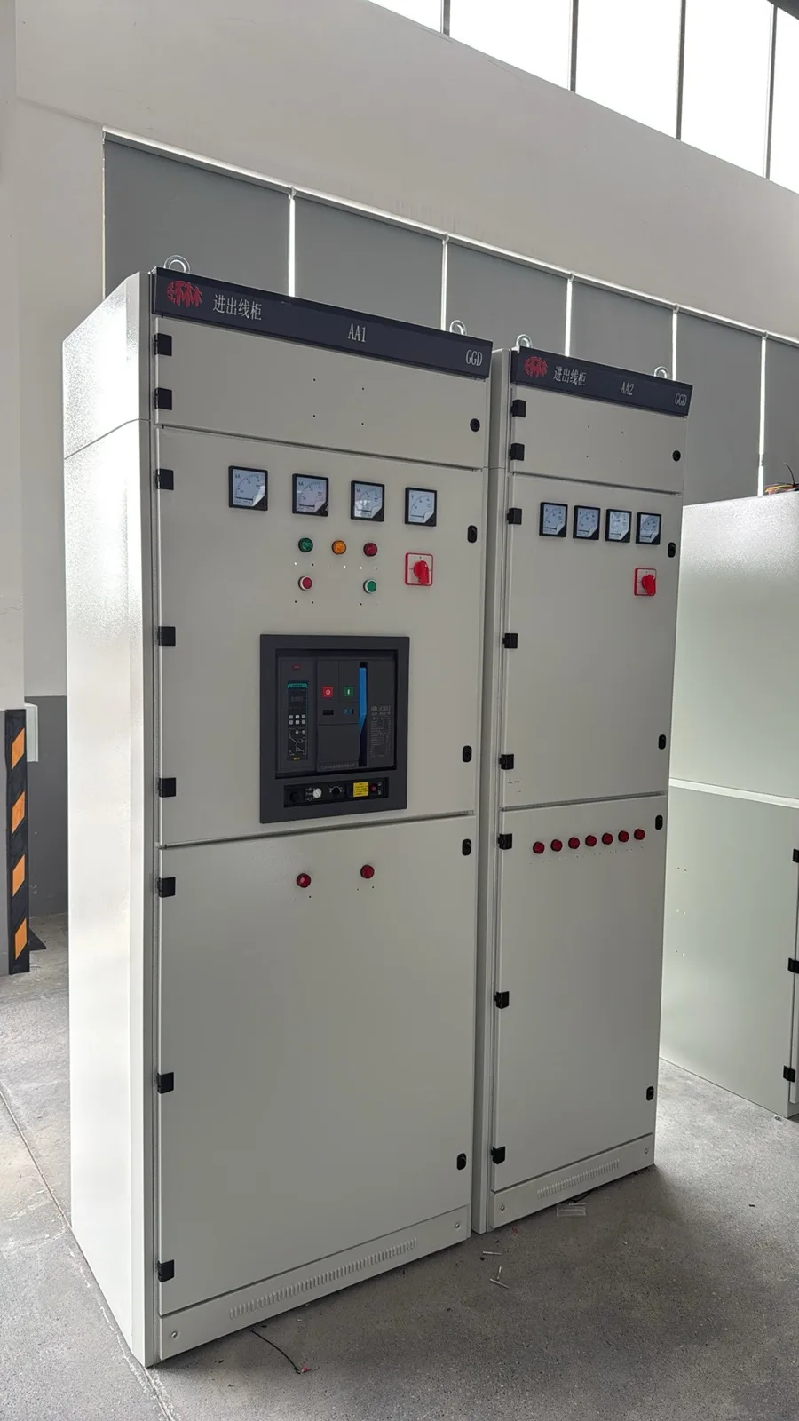
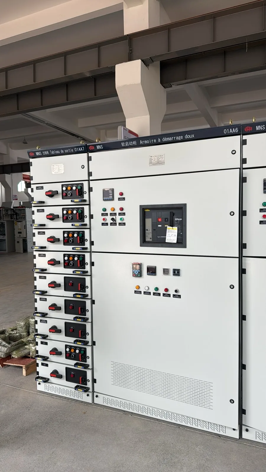
Need this guide as a reference document for your specification or tender? Our LV product catalogues and technical datasheets — covering MNS, GGD, GGJ, and BLOKSET assemblies — are available from the HARRL Download Center, and our engineering team can provide a project-specific design pack on request. Use the links below to access the catalogues or contact us for the full PDF.
Conclusion
Sound LV switchboard design comes down to verified ratings, the right form of separation, properly coordinated protection, and full IEC 61439 compliance — with enough spare capacity to grow. HARRL manufactures type-tested low voltage assemblies to IEC 61439 across withdrawable (MNS), fixed (GGD), compensation (GGJ), and modular (BLOKSET) platforms. Send us your load schedule and fault levels and our engineers will help you specify a compliant, future-ready switchboard.